Nurbs Workspace Plugin Thread

Smart people ~ Great Scripts
froo
Captain
Posts: 2554
Joined: 22 May 2009, 12:13

Nurbs Workspace Plugin Thread

Post by froo »

I've been planning on doing this for some time; just wasn't sure if it
was worth doing or not. That was the point of the Workspace poll:
whether it was worth making more plugins for the Workspace side or not.

So. On to it then.

Potential issues:
I don't believe there is a native 'line' primitive in Workspace.
But, I am thinking, I could try a couple things:
1) use DirectX calls to draw lines in the window
2) use a cylindrical tube

The lines/tubes are the 'control curves' above the nurbs surface.
We need a widget for each control point; probably will use a sphere or cube for each.

I found a good paper online, about minimizing the error between the true mathematical
nurbs surface, and the tesellated geometric representation (what trueSpace draws).
I would like to try that, but it will take some time to understand the mathematical
terminology. There's stuff there I have never seen before. :ugeek:
User avatar
clintonman
Captain
Posts: 5659
Joined: 21 May 2009, 21:08
Type the number ten into the box: 0
Location: California

Re: Nurbs Workspace Plugin Thread

Post by clintonman »

Wow, you're pretty ambitious aren't you. :worship:

You could start with curves. I think truespace modelside uses bezier curves and uses a specific type of bezier nurbs surface so the surface might be thought of as an extension of the curve math. Another advantage to starting with curves is that once you have curves it might be possible to implement an animation path system. I made some nurbs plugins a few years back, Ill see if I can find my old notes and if there's anything useful in them I'll let you know.

"2) use a cylindrical tube"
I don't understand that, but another idea for curves would be to use triangles but with only 1 edge visible to represent the curve. Of course this would be inefficient because of all the extra invisible edges.

Can't wait to see what you come up with.
Clinton Reese

http://clintons3d.com
froo
Captain
Posts: 2554
Joined: 22 May 2009, 12:13

Re: Nurbs Workspace Plugin Thread

Post by froo »

hey Clinton.
yeah, I'm ambitious alright! :)
I have a good book with supporting code as a starting point:
Focus on Curves and Surfaces. I've had it for some time, but finally
found a need for it, a couple months ago: implementing nurbs in Workspace.

I've read through most of it, and have a good understanding of the math.
The good thing is, once you understand the first couple chapters, the rest
are primarily extensions of those first few chapters.

Actually, using triangles would be more efficient than using a 'tube'.
By 'tube', I meant, a circle extruded along the curve. That would require
more vertices, and would also be more unnecessary work. I just need
a visual representation of the control points and control curves.

And you're right; starting with curves would allow for animation along a nurbs path.
When I considered that in the past, is when I realized I needed a 'way' to display
that curve. We don't have a line primitive in the Workspace. But, I am also
wondering if I can just make DirectX calls directly, and draw it in the View window.
If I could, would there be any negative issues with that? Worth thinking about.
froo
Captain
Posts: 2554
Joined: 22 May 2009, 12:13

Re: Nurbs Workspace Plugin Thread

Post by froo »

Oh forgot to say, yes, any and all helpful notes and info would be most appreciated!
Creating a nurbs object is actually the easier task I believe; trim curves are more
of a challenge though.
User avatar
clintonman
Captain
Posts: 5659
Joined: 21 May 2009, 21:08
Type the number ten into the box: 0
Location: California

Re: Nurbs Workspace Plugin Thread

Post by clintonman »

I found my notes, but there wasn't much to them. I had a printout from the rhino site:

http://www.rhino3d.com/nurbs.htm"

and some sketchy theories written down mostly trying to understand the truespace implementation. The notes say truespace is degree 3 order 4 and the curves are like a series of bezier curves glued end to end and the patches are the same thing only in 2 dimensions. Internal knots repeat 3 times and the end knots repeat 4 times and the total number of knots is num control points + order. I don't think I'm telling you anything you don't already know except maybe that modelside has the bezier style nurbs curves and surfaces.
Clinton Reese

http://clintons3d.com
froo
Captain
Posts: 2554
Joined: 22 May 2009, 12:13

Re: Nurbs Workspace Plugin Thread

Post by froo »

Ok thanks Clinton. :)
Yes that sounds familiar.
One thing I could do is allow the user to specify the order of the curve;
the basis functions are generated programmatically anyway. I am not
saying, that is what I am going to do. Just saying, it's a possibility.
I cannot recall, if I determined that was a good idea or not. I will have
to refresh my memory on that subject. The big trick, in my mind, is implementing
the trim curves. There's an easy way, and a very low-error way. The Low
error method will require some studyin on my part. :ugeek:
User avatar
Finis
Captain
Posts: 5410
Joined: 21 May 2009, 18:26
Type the number ten into the box: 0
Location: America!

Re: Nurbs Workspace Plugin Thread

Post by Finis »

Make it with the Nurbs math stuff etc. separate separate from the interface stuff so you can possibly use it to make a plugin for other 3D programs.
I prefer dangerous freedom over peaceful servitude. -- Thomas Jefferson/Jean Jacques Rousseau
Wigand
Senior Chief Petty Officer
Posts: 204
Joined: 21 May 2009, 17:38

Re: Nurbs Workspace Plugin Thread

Post by Wigand »

And you're right; starting with curves would allow for animation along a nurbs path.
Maybe you could hit two flies with one flap. (german version of: to kill two birds with one stone)
So we can get paths for workspace and animation path and nurbs. :worship:
User avatar
RAYMAN
Captain
Posts: 2547
Joined: 21 May 2009, 18:56

Re: Nurbs Workspace Plugin Thread

Post by RAYMAN »

maybe you could investigate if you can use a geometry library that is free........
You could also use the open nurbs library and the 3dm format.
Michael Gibson has always said that the quality of your nurbs application is only as good as your geometry library....
Starting with curves is a very good idea.
could you be able to use the bridge and use curves from the model side...?
The 3dm file format for modelside would also be awsome.
Peter
froo
Captain
Posts: 2554
Joined: 22 May 2009, 12:13

Re: Nurbs Workspace Plugin Thread

Post by froo »

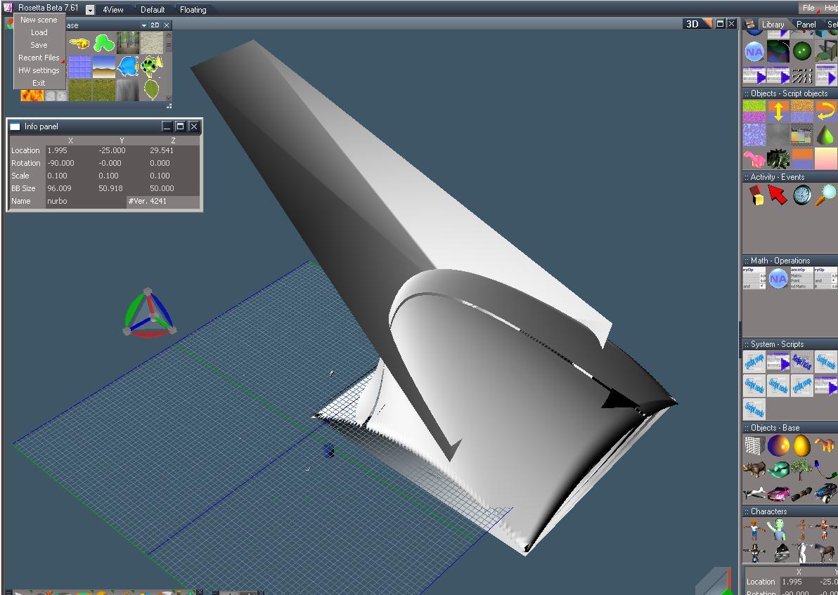
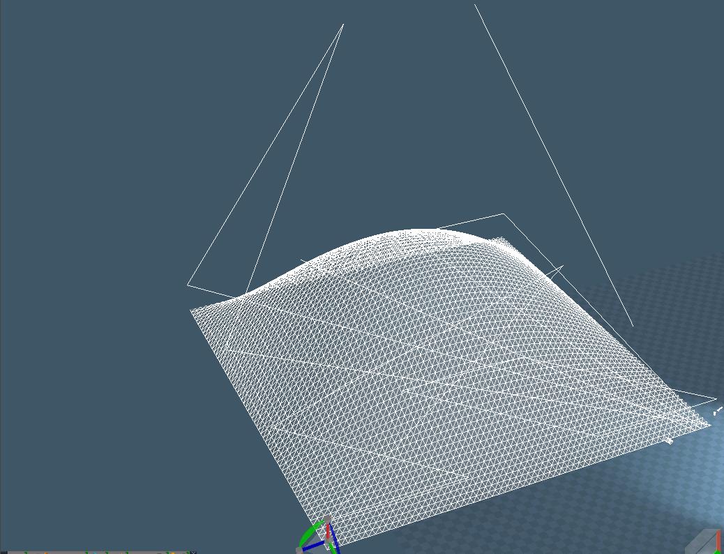
Ok; all I did with this, is copy code from the book, into the relevant area of the RnHeightField.cpp file.
RnHeightField is one of the SDK Examples. Instead of averaging the color of the bitmap to get the z height,
I inserted the Bezier surface code. Obviously this looks like hell; I just wanted to see if I could get it to work.
There are issues to be resolved with vertex indexing; that's why we have these funny artifacts.
Anyway, just wanted to show a pic and include the scene so you could have a look.
This did not take too long; about an hour or so of merging code and debugging. So that's a good thing.
Attachments
BezierSurface_Hack.zip
(128 KiB) Downloaded 58 times
BezierSurface_Hack.JPG
User avatar
clintonman
Captain
Posts: 5659
Joined: 21 May 2009, 21:08
Type the number ten into the box: 0
Location: California

Re: Nurbs Workspace Plugin Thread

Post by clintonman »

froo wrote:... Obviously this looks like hell; ....
So, how was it supposed to look?
Clinton Reese

http://clintons3d.com
froo
Captain
Posts: 2554
Joined: 22 May 2009, 12:13

Re: Nurbs Workspace Plugin Thread

Post by froo »

well it is not supposed to have the big face sticking out like that;
there are some verts out of place. But the general, smooth bubble
is the way it is supposed to look. Underneath, you will see a zig-zag pattern.
I just need to clean up the code a bit.
User avatar
clintonman
Captain
Posts: 5659
Joined: 21 May 2009, 21:08
Type the number ten into the box: 0
Location: California

Re: Nurbs Workspace Plugin Thread

Post by clintonman »

Nice, looks like you're close to solving the nurbs surface display. Any luck with curves?
Clinton Reese

http://clintons3d.com
froo
Captain
Posts: 2554
Joined: 22 May 2009, 12:13

Re: Nurbs Workspace Plugin Thread

Post by froo »

Well, that could be done, with a modification of this code.
This code generates a bezier surface, in 2 dimensions. I could just use, one dimension.
Since we do not have a line / polyline primitive (why, I don't know), I could fake it,
with a series of small, thin planes, strung together along the curve path.

BUT:
One thing I want to try is, creating a directx line strip in a workspace window.
I am not sure if that is possible or not.
User avatar
Délé
Chief Petty Officer
Posts: 84
Joined: 24 May 2009, 10:08
Type the number ten into the box: 0

Re: Nurbs Workspace Plugin Thread

Post by Délé »

Awesome! Looks like you're making some good progress Froo! :)
-Délé
http://www.GrokShockStudios.com" onclick="window.open(this.href);return false;
froo
Captain
Posts: 2554
Joined: 22 May 2009, 12:13

Re: Nurbs Workspace Plugin Thread

Post by froo »

Thanks Dele. I have a pretty good idea regarding what's wrong at present with the generated mesh.
The code combines the control mesh, and the resulting surface mesh, as one unit. Using pure DirectX,
we can get away with drawing the control portion of the mesh as wireframe, and the surface portion
as solid. I don't think we can do that with trueSpace. So I'll have to put my thinking cap on.

BTW; that portion of the mesh, that looks like it is jutting outwards? That's the control mesh, posed
that way.
User avatar
clintonman
Captain
Posts: 5659
Joined: 21 May 2009, 21:08
Type the number ten into the box: 0
Location: California

Re: Nurbs Workspace Plugin Thread

Post by clintonman »

I don't see much in the scene. Is an rsx file needed to view it?
Clinton Reese

http://clintons3d.com
froo
Captain
Posts: 2554
Joined: 22 May 2009, 12:13

Re: Nurbs Workspace Plugin Thread

Post by froo »

Well I'll be... you're right Clinton. I figured once an object was created, that was that.
Here is the modified RsExamplesPlugin.rsx file. Make sure you don't have the original
RsExamplesPlugin.rsx installed, as I have not yet changed an GUIDs.
Attachments
RsExamplesPlugin0335.zip
(42.32 KiB) Downloaded 17 times
User avatar
clintonman
Captain
Posts: 5659
Joined: 21 May 2009, 21:08
Type the number ten into the box: 0
Location: California

Re: Nurbs Workspace Plugin Thread

Post by clintonman »

Ah, I see it now. attached is a scene with flatten applied so no rsx needed to view.
Attachments
BezierSurface_Hack_Flat.zip
(182.71 KiB) Downloaded 20 times
Clinton Reese

http://clintons3d.com
froo
Captain
Posts: 2554
Joined: 22 May 2009, 12:13

Re: Nurbs Workspace Plugin Thread

Post by froo »

Cool thanks clinton! :D
Flatten... gotta remember that then.
froo
Captain
Posts: 2554
Joined: 22 May 2009, 12:13

Re: Nurbs Workspace Plugin Thread

Post by froo »

This looks considerably better; I made some fixes; the mesh is 64 x 64; the control point mesh is 4x4.
But, I was writing BOTH to a 64x64 construct. In other words, I was overwriting the surface data,
with the CP (control point) data. Fixed that. And some other small details.
But, when I try to save, it takes forever. That's not good. If I click the Exp or Default tab in the LE,
there is a long pause. Not good. If I try to Flatten this, or convert to poly, it takes forever. Not good.
But, it looks better! Makin progress! :D
The issue here is, half the triangles are inverted. I think this is because, the code orders the triangle indices,
for DirectX. I suspect trueSpace Workspace requires the triangle indexes to be ordered differently.
bez_06272010.JPG
User avatar
clintonman
Captain
Posts: 5659
Joined: 21 May 2009, 21:08
Type the number ten into the box: 0
Location: California

Re: Nurbs Workspace Plugin Thread

Post by clintonman »

Nice work. Much more pleasing shape than before.
Clinton Reese

http://clintons3d.com
froo
Captain
Posts: 2554
Joined: 22 May 2009, 12:13

Re: Nurbs Workspace Plugin Thread

Post by froo »

Thanks Clinton.
But this current version appears to be messed up; when I save, it takes 10 minutes.
When I try to convert to poly mesh, same thing. Something's wrong with it.
I tried correcting the 'ordering' of the triangle index stream, but now, I have half
the triangles inverted: the ordering should be reversed.

What I did fix though, was the problem with the control point (CP) data, overwriting
some of the surface data. I had a surface data size of: 64 x 64. The CP data is
4 x 4. The book code, uses the same data stream for both. What I really needed was
a data stream of size: (64 + 4) x (64 + 4) = 68 x 68. That solved one problem.
But the indexing messed up other things. I think, I need to start with the original height
field example, and increase the size of the data stream to 68 x 68, and not use the
indexing code. Without that, I had a surface with all triangles facing the same way.
froo
Captain
Posts: 2554
Joined: 22 May 2009, 12:13

Re: Nurbs Workspace Plugin Thread

Post by froo »

I see the indexing problem; the heightfield example does do the triangle indexing properly, already.
So I just need to remove the ad-hoc indexing approach. Then may have to rebuild this, since somewhere
I blew something up. Then it will look much better. :D
froo
Captain
Posts: 2554
Joined: 22 May 2009, 12:13

Re: Nurbs Workspace Plugin Thread

Post by froo »

Meh. Gotta start over with the Height field example. Although I know what I need to do now,
I have so much test code commented out, it's best to just, start over. Aaand somehow I managed
to change *something* which I cannot find; this compiles, runs, and does its thing, for about 10 seconds. Then, FFFOOOOMM!!! It blows up. So, better to start from scratch.
DarkScythe
Senior Chief Petty Officer
Posts: 243
Joined: 23 Sep 2009, 08:57

Re: Nurbs Workspace Plugin Thread

Post by DarkScythe »

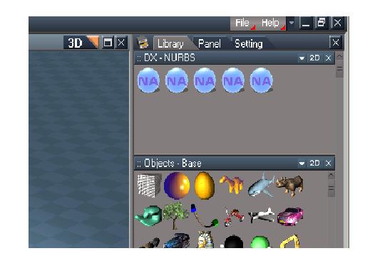
sorry for intruding may I ask what this in the library
it say dx nurbs.
Attachments
dxnurbs.JPG
froo
Captain
Posts: 2554
Joined: 22 May 2009, 12:13

Re: Nurbs Workspace Plugin Thread

Post by froo »

no prob DarkScythe. :)
I scanned those the other day as well; the one I remember, is a DX NURBs importer.
It's worth taking a closer look.
froo
Captain
Posts: 2554
Joined: 22 May 2009, 12:13

Re: Nurbs Workspace Plugin Thread

Post by froo »

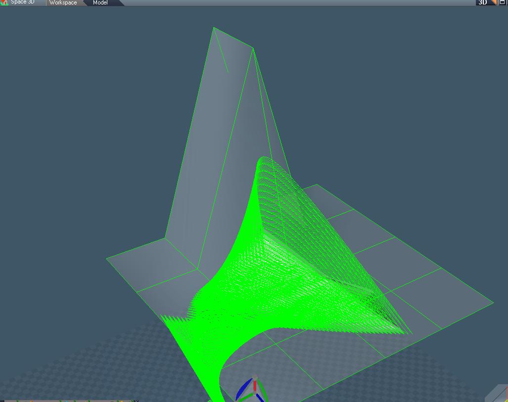
Ok; got this straightened out, except for the inverted triangles.

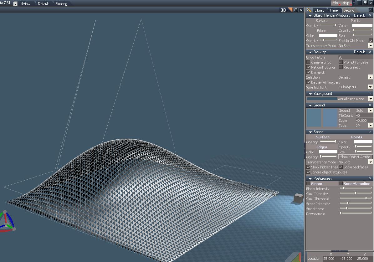
Shown is the control surface, in wireframe, along with the generated surface.
Note the raised 'bubble', where the high points of the control surface are located.
Attachments
bez_ctrl.JPG
froo
Captain
Posts: 2554
Joined: 22 May 2009, 12:13

Re: Nurbs Workspace Plugin Thread

Post by froo »

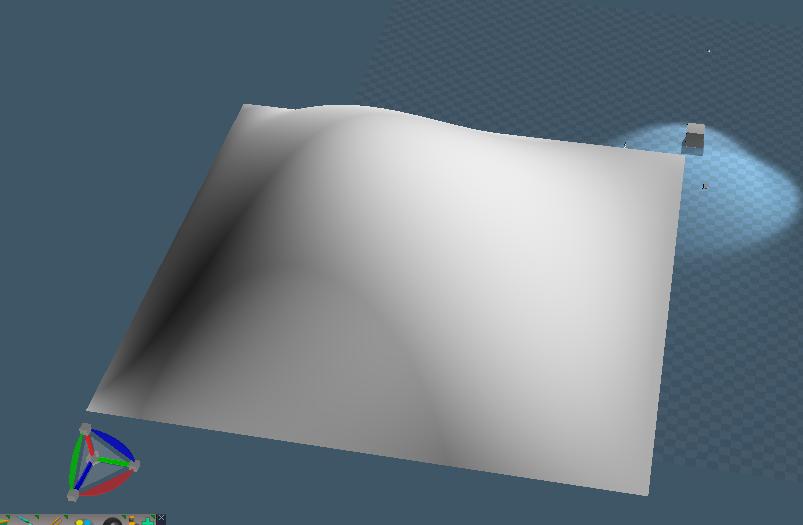
SOLVED!!!
To solve the inverted triangles problem, I reversed the order of the last 3 indices:

3
4
5

became:

5
4
3

Code: Select all

	//Fill the index for the mesh
	for (long UIndex = 0; UIndex < NUM_PATCH_VERTICES - 1; UIndex++)
	{
		for (long VIndex = 0; VIndex < NUM_PATCH_VERTICES - 1; VIndex++)
		{
			*pIndexer       = (NUM_U_POINTS * NUM_V_POINTS) + VIndex + (UIndex * NUM_PATCH_VERTICES);
			*(pIndexer + 1) = (NUM_U_POINTS * NUM_V_POINTS) + VIndex + (UIndex * NUM_PATCH_VERTICES) + 1;
			*(pIndexer + 2) = (NUM_U_POINTS * NUM_V_POINTS) + VIndex + ((UIndex + 1) * NUM_PATCH_VERTICES);
			*(pIndexer + /*3*/ 5) = (NUM_U_POINTS * NUM_V_POINTS) + VIndex + (UIndex * NUM_PATCH_VERTICES) + 1;
			*(pIndexer + 4) = (NUM_U_POINTS * NUM_V_POINTS) + VIndex + ((UIndex + 1) * NUM_PATCH_VERTICES);
			*(pIndexer + /*5*/ 3) = (NUM_U_POINTS * NUM_V_POINTS) + VIndex + ((UIndex + 1) * NUM_PATCH_VERTICES) + 1;

			pIndexer = pIndexer + 6;
		}
	}
Attachments
bezRsObj.zip
(145.04 KiB) Downloaded 25 times
bezWire.JPG
reversedTrisSOLVED.JPG
v3rd3
Lieutenant Commander
Posts: 1191
Joined: 21 May 2009, 20:04

Re: Nurbs Workspace Plugin Thread

Post by v3rd3 »

Awesome froo....
froo
Captain
Posts: 2554
Joined: 22 May 2009, 12:13

Re: Nurbs Workspace Plugin Thread

Post by froo »

Hmm I am wondering if I really need a widget as I originally intended.
Wouldn't it be smarter and easier to just switch the control surface to edit mode,
move some points, and update the generated nurbs surface accordingly? I would think so. Whether I use a widget or this suggested method, the surface needs to be updated in real time. But, I may still need a widget, just for another purpose.

What do you think?
froo
Captain
Posts: 2554
Joined: 22 May 2009, 12:13

Re: Nurbs Workspace Plugin Thread

Post by froo »

Yes, that would be best, and here's why. The control surface vertex data can be put on the output connector of control surface node. That output connector is connected to the input of the generated surface node. The data is read, and the 'output mesh' is recalculated. The MeshOut connector can be 'invalidated', forcing the mesh data to be output on the connector. Something like that, anyway.
User avatar
clintonman
Captain
Posts: 5659
Joined: 21 May 2009, 21:08
Type the number ten into the box: 0
Location: California

Re: Nurbs Workspace Plugin Thread

Post by clintonman »

Having a little conversation with yourself? :P
Clinton Reese

http://clintons3d.com
froo
Captain
Posts: 2554
Joined: 22 May 2009, 12:13

Re: Nurbs Workspace Plugin Thread

Post by froo »

Heh, yeah looks like it. :)
Actually, I will need a widget, for control point editing.
But not for the entire control surface. That may be messy.
froo
Captain
Posts: 2554
Joined: 22 May 2009, 12:13

Re: Nurbs Workspace Plugin Thread

Post by froo »

So I can do curves either of 2 ways:

1) use a 'triangle strip'.. Ok; a series of small thin planes really.
2) use the edgevisualization stream. The one that is used when we switch to point edit mode,
and the mesh is highlighted. In this case, I don't think I need triangles, or any triangle streams. Which
seems weird but I'll try it. I just need verts, the vertex stream, and the edge highlight stream.
And yes we should be able to use that data, for an animation path. That would be something that follows
this curve stuff.
froo
Captain
Posts: 2554
Joined: 22 May 2009, 12:13

Re: Nurbs Workspace Plugin Thread

Post by froo »

Ok; for one attempt, I created a plane, deleted one vertex, then set two vertices equal.
TS had no problem with that.

The issue with this is, I would have to string triangles together, with two verts of one tri,
equal to one vert of the previous.
An easier implementation would be, to use a plane (4 verts), and 2 verts are always equivalent.
That is one extra vert though, per point.
Attachments
LineFromTri.JPG
froo
Captain
Posts: 2554
Joined: 22 May 2009, 12:13

Re: Nurbs Workspace Plugin Thread

Post by froo »

Many thanks to Dele for contributing his Graph Test script.
Here's a snapshot, of a curve, in Workspace. I will put this up
on the FrooServe if you want to play with it.

Froo
Attachments
curve.JPG
froo
Captain
Posts: 2554
Joined: 22 May 2009, 12:13

Re: Nurbs Workspace Plugin Thread

Post by froo »

Been doing a lot of research and asking questions; I have a large part of the required
interfaces noted. Now I will start laying out all the pieces, and work on them one at a time.

Oh BTW I will definitely be using some widgets.
froo
Captain
Posts: 2554
Joined: 22 May 2009, 12:13

Re: Nurbs Workspace Plugin Thread

Post by froo »

Ok added a Mesh In connector to the nurbs node. That was faster than I thought. :D
Also need to export that connector, make some other connector connections. I've done that
in the OBJ package, so it's just a matter of reusing the code. Sweet.
froo
Captain
Posts: 2554
Joined: 22 May 2009, 12:13

Re: Nurbs Workspace Plugin Thread

Post by froo »

Getting back on track with this and the VRay standalone script.
Got some resolution on at least one real life issue; my wife has a gangleon
cyst on her left wrist resulting from a slip/fall which the doctor can surgically
remove. Only takes about 20 minutes or so, with 10 days recovery. Aspiration (draining it)
usually results in its return, so it's coming out.
Then she can gradually return to her normal exercise schedule, complete with full body pushups,
yoga, heavier weights, etc. Hooray! We had doubts about the whole situation, which
was a major distraction for both of us.

I've decided to start with the OBJ package as a baseline since it has a lot of the features I need for this plugin:
icons/toolbars, amongst other things.
v3rd3
Lieutenant Commander
Posts: 1191
Joined: 21 May 2009, 20:04

Re: Nurbs Workspace Plugin Thread

Post by v3rd3 »

Glad to hear that issue got resolved. I know what a toll these things can be.

Good health to you both.
froo
Captain
Posts: 2554
Joined: 22 May 2009, 12:13

Re: Nurbs Workspace Plugin Thread

Post by froo »

thanks v3rd3. :bananahi:
froo
Captain
Posts: 2554
Joined: 22 May 2009, 12:13

Re: Nurbs Workspace Plugin Thread

Post by froo »

Ok; I reviewed the OBJ package code. It would actually be better to start with the Topology example in the SDK, since it has the basics: an encapsulator, transform, and sphere node. I can replace the sphere node with the nurbs node, and go from there.

It is much cleaner, safer, and easier, to Add code, than it is, to Remove code.
froo
Captain
Posts: 2554
Joined: 22 May 2009, 12:13

Re: Nurbs Workspace Plugin Thread

Post by froo »

Ok got the topology example configured, so the sphere is converted to an editable shape WooHoo!

Code: Select all

// Make copy of the code set
	//Find Space3D package which handles 3D scene.
	CComPtr<IRsUnknownPackage> spUnkPck;
	spKernel->FindPackage(DEF_GUIDNAME(CRpSpace3DPck), &spUnkPck);
	CComQIPtr<IRpSpace3DPck> spSpace3d = spUnkPck;
	if (!spSpace3d) {
		//Space3d is not registered
		return E_FAIL;
	};

	CComPtr<IRfEditableMeshSet> ppFn;
	spSpace3d->CreateEditableMeshFnSet(&ppFn);
	CComQIPtr<IRsNode> daEncaps = spNewObjEncaps;
	CComPtr<IRsNode> dodo;// = spNewObjEncaps;
	ppFn->ConvertToEditableMesh( daEncaps, &dodo );
Next step would be, to attach the output mesh connector of the editable shape, to the input mesh of another node inside the encapsulator. By doing this, we have all the 'edit' streams we need for manipulation.

The sphere node will be replaced by the control grid/mesh for the nurbs surface.
froo
Captain
Posts: 2554
Joined: 22 May 2009, 12:13

Re: Nurbs Workspace Plugin Thread

Post by froo »

I added a node inside the topology example. Actually, for now, I have a modified 'Height field' example node, added inside the Topology Example node. The height field node is augmented with an Input Mesh connector. The height field node will be changed to something like 'Nurbs Modifier'. I don't need the height and width segment connectors. Just the input mesh connector really.

So that's the first step completed: getting a 'mesh editor' type node into the encapsulator.
Next up is connecting the editable shape and this mesh editor node, using the mesh connectors.
When I have done that, I have the edit streams.
froo
Captain
Posts: 2554
Joined: 22 May 2009, 12:13

Re: Nurbs Workspace Plugin Thread

Post by froo »

Connected.
Need to un-export the original mesh connector, and export the mesh connector from the
new nurbs modifier node.
froo
Captain
Posts: 2554
Joined: 22 May 2009, 12:13

Re: Nurbs Workspace Plugin Thread

Post by froo »

Done. All connections are in place and the mesh con exported from the nurbs modifier.
Time to check streams.
froo
Captain
Posts: 2554
Joined: 22 May 2009, 12:13

Re: Nurbs Workspace Plugin Thread

Post by froo »

Ok; asked a lot of questions, got a lot of answers... and one: OMG NO DON'T DO THAT!!!
So now it's time to research, then implement.
User avatar
Prodigy
Site Admin
Posts: 957
Joined: 21 May 2009, 14:46
Type the number ten into the box: 0
Location: Uruguay

Re: Nurbs Workspace Plugin Thread

Post by Prodigy »

Cool to follow you froo :) you are a real blogger! hahhaha

Keep in touch amigo, and keep your research quite interesting.. :worship:
๑۩۞۩๑ prodigy ๑۩۞۩๑
User avatar
clintonman
Captain
Posts: 5659
Joined: 21 May 2009, 21:08
Type the number ten into the box: 0
Location: California

Re: Nurbs Workspace Plugin Thread

Post by clintonman »

froo wrote:...... and one: OMG NO DON'T DO THAT!!!
.....
How about sharing that one? I don't want to do THAT!!! :shock: if I'm not supposed to.
Clinton Reese

http://clintons3d.com
froo
Captain
Posts: 2554
Joined: 22 May 2009, 12:13

Re: Nurbs Workspace Plugin Thread

Post by froo »

hahahaha well you can but it will burn CPU cycles.
For a Mesh Modifier node, you have to implement the IRsUnknownMeshModifier interface.
One of the methods of that interface is: GetInputConnectorId(CONID *pConId).
We have to implement that method, but, We do not call it. The Mesh Editor (MeshModifier dll) calls it.
I thought, I needed to call it, in my OnGetValue function. I do not (I already know my input mesh connector's id).
But the Mesh Modifier dll does not. So this is what the code looks like, verbatim:

Code: Select all

STDMETHODIMP CRnHeightField::GetInputConnectorId(CONID *pConId)
{
	*pConId = CON_SHAPE_INPUTMESH;
	return S_OK;
}
The input mesh connector id is required, to traverse up the chain, to the editable shape node. When we enter edit mode, we want to edit the original mesh. Similar to SDS. We won't edit the SDS mesh; we will edit the original 'control cage' type of mesh.
froo
Captain
Posts: 2554
Joined: 22 May 2009, 12:13

Re: Nurbs Workspace Plugin Thread

Post by froo »

At this point, when I enter edit mode, I get 3 custom streams in the input mesh connector.
Though I cannot see what they are, nor can I see edges highlighted when I select them. But this is progress.
I believe I need to implement some other interfaces, in order for this to happen. But it does not crash
when I click and move stuff around.
froo
Captain
Posts: 2554
Joined: 22 May 2009, 12:13

Re: Nurbs Workspace Plugin Thread

Post by froo »

dangit. had a setback.Had to reinstall WIndows on hte primary dev machine. Could not even reboot. Anyway.
stan
Master Chief Petty Officer
Posts: 584
Joined: 21 May 2009, 17:20

Re: Nurbs Workspace Plugin Thread

Post by stan »

sounds like a setback :bananadevil:
froo
Captain
Posts: 2554
Joined: 22 May 2009, 12:13

Re: Nurbs Workspace Plugin Thread

Post by froo »

yeah done with all that noise.
froo
Captain
Posts: 2554
Joined: 22 May 2009, 12:13

Re: Nurbs Workspace Plugin Thread

Post by froo »

Ok so I implemented the IRsUnknownMeshModifier and IRsMeshModifierNotify interfaces; the desired functions are getting called. But when I enter edit mode (which activates the Mesh Modifier types of interfaces), I do not get edges, points, faces, triangles selected, nor highlighted. So I am missing something.

Maybe I need to access the selection streams, and 'do something' with them.
froo
Captain
Posts: 2554
Joined: 22 May 2009, 12:13

Re: Nurbs Workspace Plugin Thread

Post by froo »

Update: asked lots of questions, got lots of answers. I understand this much better now.
When I used the GetNumEdgeWeights function, I was expecting to get the number of edges
I selected. That is not correct. This is really the number of triangles in the Input Mesh.
Each triangle edge has a weight. So, this is the 'end' value that I need to use, in a for loop.
I have to access the edge weight stream of the input, and get the edge weight of each edge.
A weight of 0 = Not selected, a weight of 1 = Selected.

I take the edge weight stream of the input mesh, and essentially transfer it to the output mesh.
This is not a simple 'copy' though, because the topology of the input mesh may have changed: a user may add/delete edges, verts, triangles, etc. But for now, I will handle the simple case, in which there are no topology changes. I will get that working first, then move on to handle mesh edits.

I will have to draw this up, and make an article here, and at truespaceplugins.com. But, essentially, the input mesh (editable shape) must be the control surface. The Output mesh must be: the input mesh (control surface) PLUS the generated output mesh. That way the control surface is available, for making edit selections. Otherwise, we can't see the control mesh.
User avatar
clintonman
Captain
Posts: 5659
Joined: 21 May 2009, 21:08
Type the number ten into the box: 0
Location: California

Re: Nurbs Workspace Plugin Thread

Post by clintonman »

froo wrote:U....

I will have to draw this up, and make an article here, and at truespaceplugins.com. ....
Looking forward to the writeup. :bananathumb:
Clinton Reese

http://clintons3d.com
froo
Captain
Posts: 2554
Joined: 22 May 2009, 12:13

Re: Nurbs Workspace Plugin Thread

Post by froo »

Nice! I have to implement it first. I understand the concepts now, but need to get it 'working'.
:bananacheers:
froo
Captain
Posts: 2554
Joined: 22 May 2009, 12:13

Re: Nurbs Workspace Plugin Thread

Post by froo »

asked lots of questions, got lots of answers. Some of the answers, still require more discussion.
But, I have enough now, to at least get some code in place. It's time to start coding in earnest.

At present, the editable shape is a cube. That's not what we need for all purposes. It may
be useful at some point, but not now. I will comment that code out, because, I may need it
in the future. For example, the user may want to select from a number of control mesh types (maybe, not sure yet):
plane, cube, sphere, saddle, that type of thing.

The basic idea is this: editable shape is the control mesh. Mesh modifier node outputs
the control mesh, Plus the generated nurbs mesh. When the user enters edit mode, they
select points/edges/triangles from the Output mesh. If they select geometry on the nurbs mesh,
I must ensure the correct control mesh geometry gets selected as well. More on this later.
froo
Captain
Posts: 2554
Joined: 22 May 2009, 12:13

Re: Nurbs Workspace Plugin Thread

Post by froo »

Cleaned up the code a bit; removed commented out code that was for test purposes.

First up, I need to create a new node type: Nurbs Control Surface. It will be based on the HeightField example,
for a couple reasons. It creates a node already (nice). It has resx and resy inputs (nice) - this sets the resolution
of the control grid/surface. I don't need a bitmap connector, so that'll have to go.

This node will be converted to an editable shape, and serve as the input to the nurbs modifier node.

In the nurbs modifier node, the nurbs control surface will be the first portion of the output mesh.
The output mesh will consist of the nurbs control surface, Plus the generated nurbs mesh.
The reason for this is, when we make a selection, we are selecting from the Output mesh connector.
That's the short version of a long story. The long story will be documented in an article which I will
write when I can.
froo
Captain
Posts: 2554
Joined: 22 May 2009, 12:13

Re: Nurbs Workspace Plugin Thread

Post by froo »

Control surface created, though needs some cleanup.
froo
Captain
Posts: 2554
Joined: 22 May 2009, 12:13

Re: Nurbs Workspace Plugin Thread

Post by froo »

Control surface cleaned up. At present this is a 4 x 4 mesh. Will add capability to change this later.

Currently, in the process of passing this mesh, as the input mesh to the nurbs surface generator node.
I need to access the mesh data, and pass it on, to the output mesh connector. Working that now.
The output is: input control mesh + generated mesh.
froo
Captain
Posts: 2554
Joined: 22 May 2009, 12:13

Re: Nurbs Workspace Plugin Thread

Post by froo »

This is unexpected, but interesting looking.
Attachments
unexpected.JPG
froo
Captain
Posts: 2554
Joined: 22 May 2009, 12:13

Re: Nurbs Workspace Plugin Thread

Post by froo »

Here we have the input mesh (Control shape) included with the output. But,
as you can see, there is still work to do. The control shape points are not in the
correct places. But this is progress; the control mesh is now part of the output.
Attachments
inMeshIncluded.JPG
User avatar
marcel
Captain
Posts: 2247
Joined: 21 May 2009, 19:52
Type the number ten into the box: 0
Location: paris - France

Re: Nurbs Workspace Plugin Thread

Post by marcel »

I wish you have enought courage to complete this work. This reminds me of the time when I was doing the programming. This can be exciting, exhilarating but also exhausting and depressing when you get the best of yourself. :bananatyping:
Design - illustration - Animation
http://www.crea-vision.fr
froo
Captain
Posts: 2554
Joined: 22 May 2009, 12:13

Re: Nurbs Workspace Plugin Thread

Post by froo »

Merci Marcel! :D :bananacheers:
Yes, I will finish this. I have a long way to go; lots to add.
I believe I know the problem with the disorganized control mesh.
The original example used individual indexes (Long Integers) for the triangle indexes.
But trueSpace uses Triples: one index, for each corner of the triangle.
So to get the example to work, I did a little hack: 3 Long integer indexes
are equivalent to one RtTriple. So, I got it to work before.

Now, I do not need to use the old example. Instead, I used the height field example as a starting
point for the control mesh, and that uses RtTriples. BUT: I still have that old example
code, that is trying to use the generic Long Integers for indexing. That has to be fixed.
That is what is screwing up the drawn control mesh. I did not have time this AM to incorporate
the fix; hopefully tonight. :)

Once this part is working, I can add all the streams required for editing. I need those, in order to
make selections and actually push and pull verts/triangles around. The idea here is, you can
select parts of either the control mesh, or the surface. If a selection is made on the surface, then the
associated parts of the control mesh must be selected as well. There's a stream for that. :D It'll be
good to see that in action.
froo
Captain
Posts: 2554
Joined: 22 May 2009, 12:13

Re: Nurbs Workspace Plugin Thread

Post by froo »

Ok. Got that straightened out for the most part.
Here's a snapshot.
Had trouble earlier; got crashes. I figured, I had an input mesh, and a generated mesh. Sooo...

Input triangles + gen'd triangles = ok
=input verts + gen'd verts = OK

/******************
NOT SO.
I had to recalculate the counts. Seems puzzling to me. But it worked. Ok whatever.
*//////////////////////////
This is wrong wrong wrong.

EDIT: Ok I gotta fix this. I am having an over-run somewhere.
Attachments
controlsurface_Better.JPG
froo
Captain
Posts: 2554
Joined: 22 May 2009, 12:13

Re: Nurbs Workspace Plugin Thread

Post by froo »

looks like I have the u, v, x, y, and z data mixed up between the control shape and the nurbs shape.
Note the twisting effect.

This reminds me of the classic Star Trek episoe where this giant 'Doomsday machine' that looks like a
a moldy cornucopia is turning to destroy the Enterprise...
froo
Captain
Posts: 2554
Joined: 22 May 2009, 12:13

Re: Nurbs Workspace Plugin Thread

Post by froo »

Ok I think I got this straightened out. My indexing, for the nurbs mesh, is off by -1.
In other words, the first row is fine: elements 0 - 63.
But, when I start the next row, I should start at element 64, and go to 127.
I am not, due to a bug. I am starting at element 63 (the last element, in the first row),
and going to the next-to-last element, in the current row:

+..................................................................+.
+..................................................................+.

and it screws the whole thing up.

This equation:

Code: Select all

long Current = ( inVertCount_U * inVertCount_V ) + (U * segsx ) + V;
Should be:

Code: Select all

long Current = ( inVertCount_U * inVertCount_V ) + U * (segsx + 1) + V;
See the difference? I have to calculate an offset, for each row, so I can jump down to that row and start processing.

Perhaps more aptly put, this is what I need:

segsx = # segments in x-direction
Vertsx = segsx+1 = # verts in x direction

Code: Select all

long Current = inVertCount_U * inVertCount_V + U * Vertsx + V;
froo
Captain
Posts: 2554
Joined: 22 May 2009, 12:13

Re: Nurbs Workspace Plugin Thread

Post by froo »

There. Got this straightened out.

Couple issues I had: After calculating the control mesh triangle indexes, I
thought I had the correct index, but I was wrong. I need to set the index to:

ptr = (inVertsX * in VertsY);

for a control mesh with 5x5 = 25 verts, ptr should be: 25; but I was getting: ptr = 20.
That was one problem.

The other problem was, when I was calculating the vertex data. I had this:

pVertices[Current].x += BU[UStep] * BV[VStep] * pVertices[UStep * 4 + VStep].x;

The value '4' here was originally intended for use with a control mesh with 4x4 vertices. I replaced that equation with this:

pVertices[Current].x += BU[UStep] * BV[VStep] * pVertices[UStep * inVertCount_U + VStep].x;

Note the replacement of '4' with: inVertCount_U.

Here is a snapshot of the now correct output mesh, which is composed of the control surface, and resulting nurbs mesh:
Attachments
nurbs_correct.JPG
froo
Captain
Posts: 2554
Joined: 22 May 2009, 12:13

Re: Nurbs Workspace Plugin Thread

Post by froo »

Ok now I am trying to understand, why in that last pic, the generated mesh only spans 3 segments of the control surface.

This is the original; notice, there are 3 segments, and the generated mesh spans all 3 segments in each direction.
Attachments
ThreeSegments.JPG
froo
Captain
Posts: 2554
Joined: 22 May 2009, 12:13

Re: Nurbs Workspace Plugin Thread

Post by froo »

I believe the reason for this artifact is, the relationship between the control mesh and generated mesh is 'weak': there is no dependency between the scaling of the input mesh and generated mesh yet.

To remind myself, the first goal was, get the input control mesh and generated mesh combined correctly on the output mesh connector.

The next goal is, make the scaling for both input and generated meshes the same; make the generated mesh data more dependent on the input mesh data.
froo
Captain
Posts: 2554
Joined: 22 May 2009, 12:13

Re: Nurbs Workspace Plugin Thread

Post by froo »

heh that's not quite right. The current implementation is based on, the use of 16 control points (3 segments in x, 3 segments in y = 4 control points in x, 4 in y).
For 4 control points, I have 4 basis functions. And my nested for loop, must loop through these control points for calculation. If I want 5 control points in x and y, I need 5 basis functions and 5 derivative basis functions. Note that this current implementation is not a NURBs surface; it is still a Bezier surface. No problem. At least I know what's wrong.
froo
Captain
Posts: 2554
Joined: 22 May 2009, 12:13

Re: Nurbs Workspace Plugin Thread

Post by froo »

Ok; using 5 basis functions for 5 control points (a 5th order polynomial) is a bad idea. Because according to that logic, I would need a 6th order polynomial for 6 control points, and on and on.
A smarter approach is to use a 3rd order polynomial, repeatedly. But that's for Bezier surfaces anyways, not nurbs surfaces. We can create bezier surfaces using nurbs equations anyways.
So, I will keep that in mind during the development process. I have not decided yet if there is value/usefulness in creating bezier surfaces yet. There may be.

So. My next goal is, making selections, and getting those selections highlighted. That is a fairly straightforward process: transfer (i.e. Copy) the visualization, selection, and lookup streams from the mesh modifier input mesh connector, to the mesh output connector.

The following goal may be a bit more complicated: addition of new geometry requires a calculation of the additions into the aforementioned streams.
User avatar
marcel
Captain
Posts: 2247
Joined: 21 May 2009, 19:52
Type the number ten into the box: 0
Location: paris - France

Re: Nurbs Workspace Plugin Thread

Post by marcel »

He he...i hope this leaves you time to sleep. ;)
Design - illustration - Animation
http://www.crea-vision.fr
froo
Captain
Posts: 2554
Joined: 22 May 2009, 12:13

Re: Nurbs Workspace Plugin Thread

Post by froo »

:)
Yeah I get some sleep. I just spend some time on it each day if at all possible.

Last night I copied the visualization and selection streams from the input connector to the output. I saw nothing selected/highlighted though. That's because, I also need to copy the 'Lookup' streams. We can only see the vertexes, triangles, and edges that are on the Output connector of the node. When we make a selection, that is where the selection is made.
BUT: I need to push (pass) those selections, back to the Input connector, so they are then 'reprocessed' to get highlighted. Sounds convoluted I know. But that explains why I don't see any highlights. I am at the point now, where I need to draw a picture.
User avatar
marcel
Captain
Posts: 2247
Joined: 21 May 2009, 19:52
Type the number ten into the box: 0
Location: paris - France

Re: Nurbs Workspace Plugin Thread

Post by marcel »

froo wrote: I am at the point now, where I need to draw a picture.
Is the best way to test and improve what we would do with. The most important is to be sure of the usefulness of a tool. Hard work of programming sometimes hides this aspect because we are too busy solving a problem.
Design - illustration - Animation
http://www.crea-vision.fr
froo
Captain
Posts: 2554
Joined: 22 May 2009, 12:13

Re: Nurbs Workspace Plugin Thread

Post by froo »

Yes that is correct Marcel. Though, I am not at the point yet, where I can sketch out the user-controls for the tool. This still a coding issue; I need to draw a diagram that shows the flow of data, because it is not yet completely clear to me. I believe I need to use a couple streams called:

IRdGeometryIdentificationStream
IRdGeometryIdentificationTriangleStream

these data streams, I think, provide the 'lookup' information I need; it's easier to understand if it's in a picture. :)
You enter edit mode, and select, say, vertices. That selection is on the output connector. These streams (I think) provide a mapping, from the selected output vertices, to the input connector.

BTW there is an interesting stream, called IRdMeshSelection. Of particular interest is the function:
IRdMeshSelection::TranslateToInput
which, if functional, maps the selection from output mesh to input mesh, using internal lookup streams. I will keep that one in mind.
User avatar
clintonman
Captain
Posts: 5659
Joined: 21 May 2009, 21:08
Type the number ten into the box: 0
Location: California

Re: Nurbs Workspace Plugin Thread

Post by clintonman »

So complicated... I hope your picture fits on one page. :bananatyping: ;)
Clinton Reese

http://clintons3d.com

Return to “Scripts and SDK”