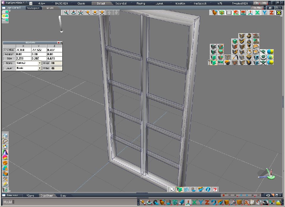
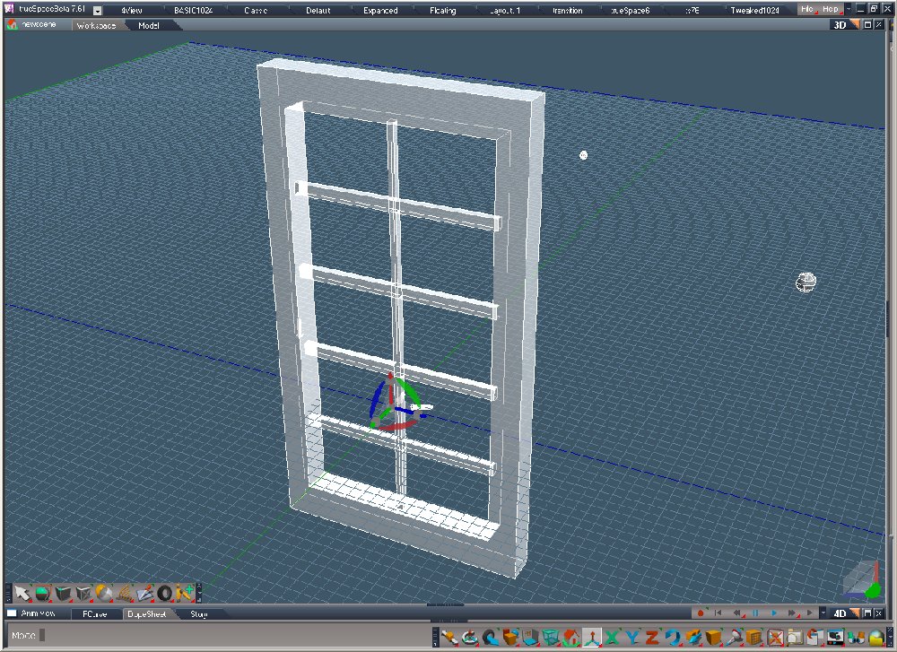
How to construct this window.

Technical questions, etc..
fahembree
Chief Petty Officer
Posts: 108
Joined: 22 May 2009, 02:28

How to construct this window.

Post by fahembree »

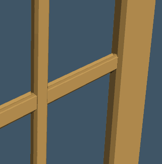
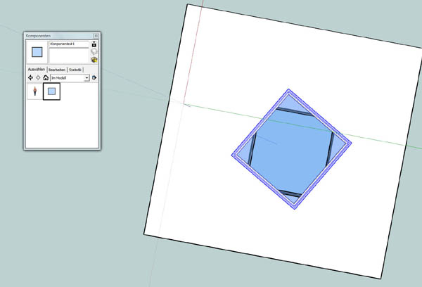
How do you construct this window in Ts. I have tried boolean subtraction :) but it always messes up
on the the last object to subtract (using model space). I have tried the same in workspace
and it works there but the resulting object will have extra faces when I try to go back to
modelspace side. I thought this would be easy but apparenly its not. The window came from a model that I downloaded from the tutorial on Vray interior rendering.
Attachments
Window-3.jpg
Perfect_Window.jpg
User avatar
spacekdet
Captain
Posts: 1810
Joined: 27 May 2009, 15:00
Type the number ten into the box: 10
Location: On the day shift at the Utility Muffin Research Kitchen

Re: How to construct this window.

Post by spacekdet »

I wouldn't use boolean at all, except maybe to cut the hole in the wall and trim the 45 degree angles where the trim pieces miter together.
I'd build it just like you were building it out of wood.

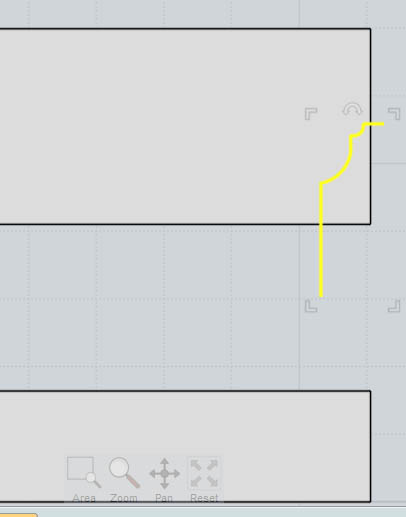
I'd first draw the profiles (Draw Curve) of the various pieces- the outside casing, the molding on the edge of the glass and then moldings in the middle. Think cross-sections.
These I'd then convert to polygon and sweep.
Then it's just a matter of scaling/ lining up all the various parts.
Make the miter joints by trimming off the ends at a 45 degree angle with a simple cube.
I usually use Point Edit and select/ move the bits at the ends if I need to do any fine tuning after mitering the corners... scaling a 45 degree angle changes the angle.
4 pane view and Grid Snap are your friends in something like this.
User avatar
marcel
Captain
Posts: 2247
Joined: 21 May 2009, 19:52
Type the number ten into the box: 0
Location: paris - France

Re: How to construct this window.

Post by marcel »

Yes, no need boolean for this kind of model. first it is easier to change the design with different objects, second it is easier to adjust the uvmap around each part separately. booleen is necessary if you want a transparency object but it is not the case here.
ps: if you want to do a good boolean object on the model side, the best is to merge all the objects that you need for the holes (even if they have no intersection) then create all the holes in one time with the result of the merged objects. you will have less problem than to do the holes one by one.
Design - illustration - Animation
http://www.crea-vision.fr
fahembree
Chief Petty Officer
Posts: 108
Joined: 22 May 2009, 02:28

Re: How to construct this window.

Post by fahembree »

I finally got it constucted but I needed to use workspace side. I started with one rectangle (casing) and mitered the corners
using boolean subtract to get a 45 degree angle at each end, then sweep the ends until I had 4 sides. Then I selected the inside faces and used quad divide face. Then used the form bridge face and then came back and deleted all of the exta edges and vertices. And this shape transfers ok back to model side without problems. I first tried boolean with all of the cubes merged to delete as one object but it did not work, as it also got extra faces added. :)
Attachments
Window-5WS-1.jpg
Window-5.jpg
Window-5WS.jpg
User avatar
Emmanuel
Chief Warrant Officer
Posts: 670
Joined: 14 Jun 2009, 06:47

Re: How to construct this window.

Post by Emmanuel »

You can use the boolean tool in Modeler side but the main window frame (the cube you make holes in) should have more edges on it : modeler's boolean get lost if there is not enough polygonal informations where the volume is cut off.

How to add details ?
1. In point edit mode, select one face on the side of your window frame.
2. Pick up the Slice Object By Selected Face/Plane tool, and drag the mouse to draw edges at the middle of the places where you want to cut off the frame. Repeat this operation to add enough slices/edges.
3. Now you can boolean, but make sure to check off the Delete Edge option in boolean options panel.

That trick, when I discovered it, changed my life with booleans :)
User avatar
RAYMAN
Captain
Posts: 2547
Joined: 21 May 2009, 18:56

Re: How to construct this window.

Post by RAYMAN »

you see thats the workflow that most people that prefer to use a simple to use application
like Truespace wants to be dont realise that polygon modeling is polygon modeling.....
While what you guys realy want is modeling with nurbs....
If you want to use that initial modeling technic of cutting into a block get Moi3d or use the free Sketchup
They are made for excessive use of booleans not poly modelers.
This problem pops up every month ....... ;)
PS Even Weta uses nurbs tools like Mirai like on the lord of the rings trilogy...
http://www.gamasutra.com/view/feature/2 ... _weta_.php"
or the nurbs tools inside Maya.
maya even lets you switch back and forth from nurbs to poly......
Some shapes like th wheel are very difficult to make not using booleans....
Attachments
felge.jpg
door.gif
door.gif (228.75 KiB) Viewed 6213 times
door1.jpg
Last edited by RAYMAN on 12 Mar 2010, 18:29, edited 1 time in total.
User avatar
Finis
Captain
Posts: 5410
Joined: 21 May 2009, 18:26
Type the number ten into the box: 0
Location: America!

Re: How to construct this window.

Post by Finis »

The Boolean system can produce unwanted artifacts but usually works well on simple objects. Do group (glue) things together as noted above.

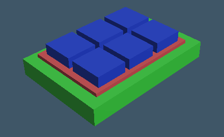
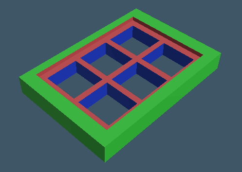
I had no trouble with Booleans below. TS7.6 model side. The blue boxes are glued as siblings. I subtracted the blue from the green and then the red from that. Delete edges on. There are several polygons with more than 4 sides so that might need clean up if it is an issue.

I would use non-Boolean techniques. as others already noted, to make this window.
Attachments
Image7.gif
Image7.gif (3.52 KiB) Viewed 6195 times
Image5.gif
Image5.gif (4.35 KiB) Viewed 6195 times
Image4.gif
Image4.gif (5.2 KiB) Viewed 6197 times
Last edited by Finis on 12 Mar 2010, 18:11, edited 1 time in total.
I prefer dangerous freedom over peaceful servitude. -- Thomas Jefferson/Jean Jacques Rousseau
User avatar
Finis
Captain
Posts: 5410
Joined: 21 May 2009, 18:26
Type the number ten into the box: 0
Location: America!

Re: How to construct this window.

Post by Finis »

Non Boolean. TS 6 model side.

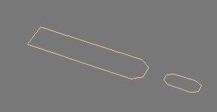
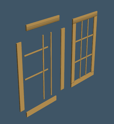
I made profiles with Add Polyline. Then made boards with the sweep tool. Then resized and arranged them with Move, Scale, and Rotate tools as well as the Object Info panel. You could make detailed profiles like router bits make and create realistic woodwork this way.

Maybe Boolean union to fuse them into one object if need but probably just gluing the assembly together.
Attachments
outline.gif
outline.gif (736 Bytes) Viewed 6196 times
assembly.gif
assembly.gif (7.96 KiB) Viewed 6195 times
detail.gif
detail.gif (5.01 KiB) Viewed 6194 times
I prefer dangerous freedom over peaceful servitude. -- Thomas Jefferson/Jean Jacques Rousseau
User avatar
RAYMAN
Captain
Posts: 2547
Joined: 21 May 2009, 18:56

Re: How to construct this window.

Post by RAYMAN »

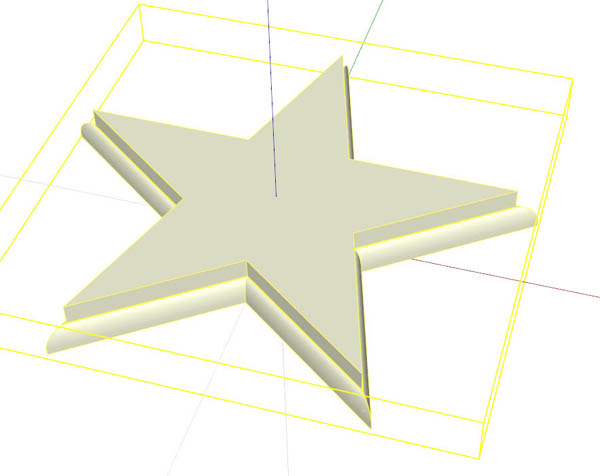
The cutter - cutter method has advantages when things start to get more complicated...
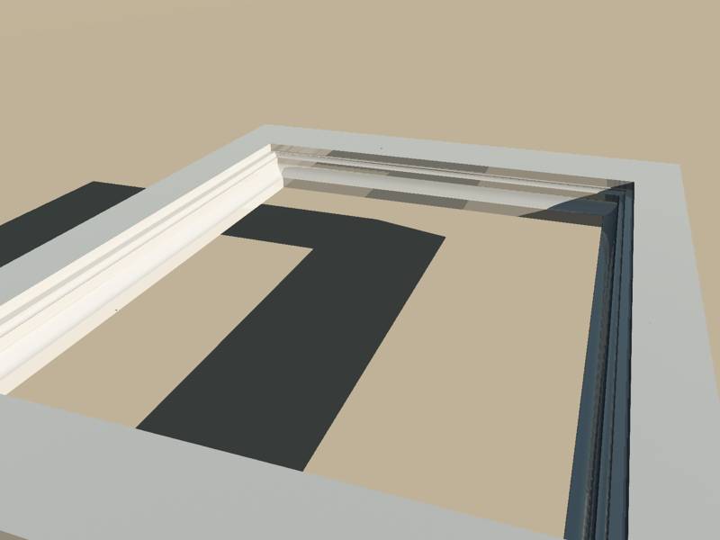
like in the example where i cut the first block with a profile and then used that block to cut a negative in a door...
Attachments
1.jpg
frame2.jpg
frame3.jpg
User avatar
RAYMAN
Captain
Posts: 2547
Joined: 21 May 2009, 18:56

Re: How to construct this window.

Post by RAYMAN »

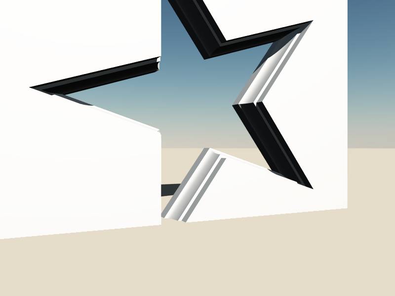
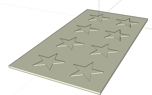
or this
Attachments
star.jpg
User avatar
Finis
Captain
Posts: 5410
Joined: 21 May 2009, 18:26
Type the number ten into the box: 0
Location: America!

Re: How to construct this window.

Post by Finis »

Is that cutter a Moi3D tool Rayman?
I prefer dangerous freedom over peaceful servitude. -- Thomas Jefferson/Jean Jacques Rousseau
User avatar
RAYMAN
Captain
Posts: 2547
Joined: 21 May 2009, 18:56

Re: How to construct this window.

Post by RAYMAN »

Finis wrote:Is that cutter a Moi3D tool Rayman?
No you make your own tools inside moi3d thats the point of it....
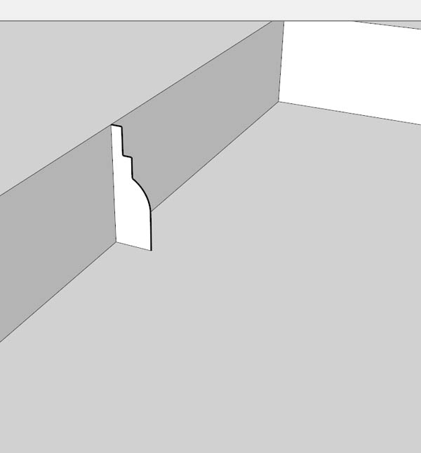
Thats the point of booleans on top of booleans..... You only make a profile you then make a curve of any kind... that makes a profiled star as an example.
You then use that as a drill inside your board.......
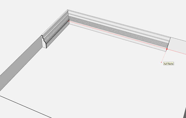
The sky is the limit for what you do with it. By the way the free Sketchup can do the same thing. Its called follow tool there.
The difference in Sketchp is that if you make your booleans you have to delete the faces you dont want.
Peter
User avatar
RAYMAN
Captain
Posts: 2547
Joined: 21 May 2009, 18:56

Re: How to construct this window.

Post by RAYMAN »

Here is how it works in (free)sketchup.... with the follow tool..
Attachments
star0.jpg
star2.jpg
star3.jpg
User avatar
RAYMAN
Captain
Posts: 2547
Joined: 21 May 2009, 18:56

Re: How to construct this window.

Post by RAYMAN »

and boolean funktion...which is actually a merge function.
Attachments
star4.jpg
User avatar
RAYMAN
Captain
Posts: 2547
Joined: 21 May 2009, 18:56

Re: How to construct this window.

Post by RAYMAN »

But much easier is to make it the component way in Sketchup
If your window does not go through your model you can make a recess of a window once and store that recess as a component.
when you pull that recess onto a surface in the future for any project it is automatically booleaned . If the bottom face is a glass materila you can look inside if you
put the same recess onto the back of your door you can look through that door you can even scale and turn that recess..
Attachments
profile1.jpg
profile 2a.jpg
profile 4.jpg
User avatar
marcel
Captain
Posts: 2247
Joined: 21 May 2009, 19:52
Type the number ten into the box: 0
Location: paris - France

Re: How to construct this window.

Post by marcel »

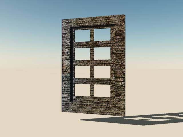
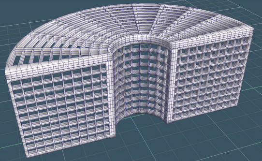
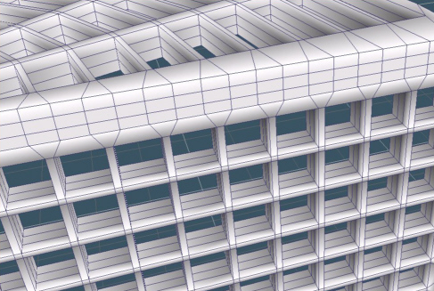
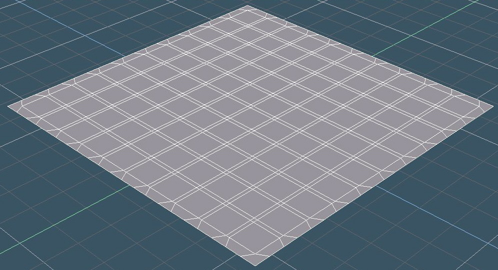
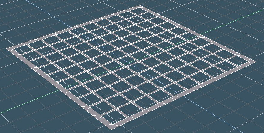
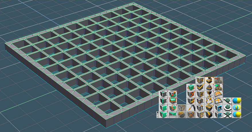
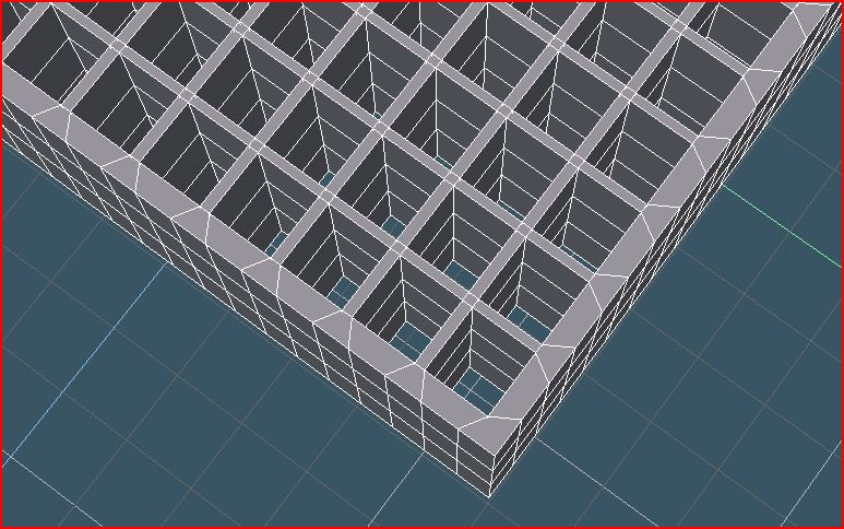
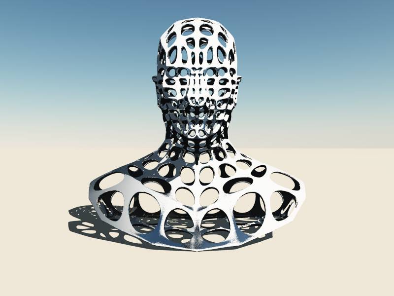
Here is an object with 400 holes and only quad made with Truespace (about 10 minutes of work). The secret? i don't use boolean for that! :mrgreen:
Attachments
400 holes.jpg
details.jpg
Design - illustration - Animation
http://www.crea-vision.fr
User avatar
marcel
Captain
Posts: 2247
Joined: 21 May 2009, 19:52
Type the number ten into the box: 0
Location: paris - France

Re: How to construct this window.

Post by marcel »

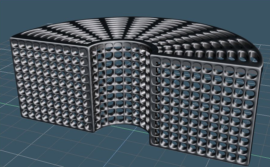
The same with SDS
Attachments
SDS.jpg
Design - illustration - Animation
http://www.crea-vision.fr
User avatar
RAYMAN
Captain
Posts: 2547
Joined: 21 May 2009, 18:56

Re: How to construct this window.

Post by RAYMAN »

Thats what I meant before If you use polygonal tools try to model it rather then boolean it....
But you are limited to pretty simple shapes as holes...
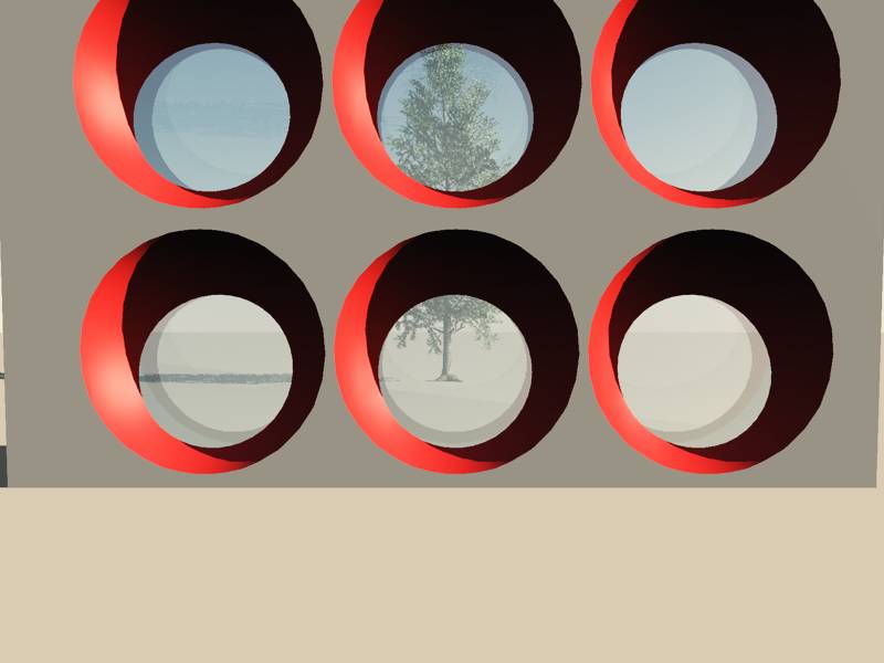
While with the other method it can be assymetric windows too like in this case hudreds of them just drag and drop on any surface..
Attachments
bullauge.jpg
User avatar
marcel
Captain
Posts: 2247
Joined: 21 May 2009, 19:52
Type the number ten into the box: 0
Location: paris - France

Re: How to construct this window.

Post by marcel »

No limit to create complex holes with my method because there is no boolean operation. First i use plane, then erase some polygones (the holes), then select all faces and sweep all the face in the same time to create a volume. I use also Illustrator and import files into truespace if i need to draw a complex "holes". Illustrator is like a plugin for me. The interest is all my customers have it. ;)
Design - illustration - Animation
http://www.crea-vision.fr
fahembree
Chief Petty Officer
Posts: 108
Joined: 22 May 2009, 02:28

Re: How to construct this window.

Post by fahembree »

>>First i use plane, then erase some polygones (the holes), then select all faces and sweep all the face in the same time to create a volume. I use also Illustrator and import files into truespace if i need to draw a complex "holes". Illustrator is like a plugin for me. The interest is all my customers have it. <<

This is a great thread. Good thing about truedpace forum is you get answers from the experts.
Marcel. I don't understand what you mean by first draw a plane then erase polygons for the holes, as a plan is just 4 edges. How do you add the holes to the plane?

I made these windows with 2 cubes and boolean subracted athe second smaller one fron the larger and use the array to create the walls. Its looks ok except sds gave a different result than yours. :)
Attachments
win-bldg-02.jpg
win-bldg-02R.jpg
User avatar
marcel
Captain
Posts: 2247
Joined: 21 May 2009, 19:52
Type the number ten into the box: 0
Location: paris - France

Re: How to construct this window.

Post by marcel »

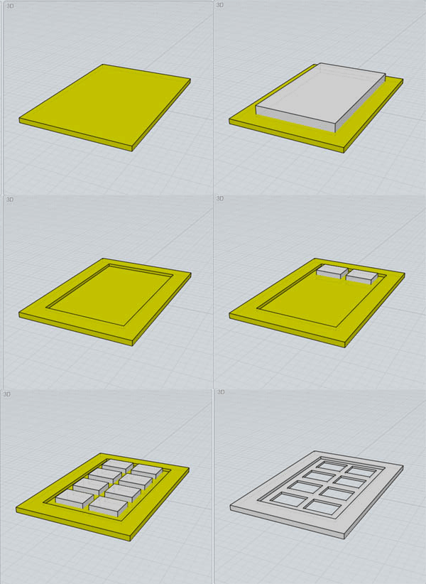
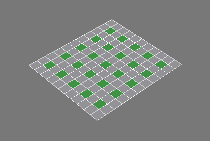
Is totally different. you use one object per windows. mine is only one object for all the windows. it is why SDS is different. here is how to do:
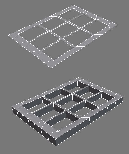
first create a plane (single side)(1), draw(2) and erase the polygones to create holes(3).
Attachments
01.jpg
02.jpg
03.jpg
Last edited by marcel on 13 Mar 2010, 08:04, edited 1 time in total.
Design - illustration - Animation
http://www.crea-vision.fr
User avatar
marcel
Captain
Posts: 2247
Joined: 21 May 2009, 19:52
Type the number ten into the box: 0
Location: paris - France

Re: How to construct this window.

Post by marcel »

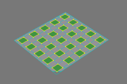
Now select all the faces and sweet the whole (4). Before use SDS, don't forget to erase the face inside the holes created when you use the sweep tool (5). It is simple, you need one click because it is only one face to erase. Now you have a clean object useful for SDS (6).
Attachments
04.jpg
05.JPG
06.jpg
Design - illustration - Animation
http://www.crea-vision.fr
User avatar
marcel
Captain
Posts: 2247
Joined: 21 May 2009, 19:52
Type the number ten into the box: 0
Location: paris - France

Re: How to construct this window.

Post by marcel »

And you can see the object have only quad. you will have no problem with it.
Attachments
07.jpg
Design - illustration - Animation
http://www.crea-vision.fr
User avatar
Finis
Captain
Posts: 5410
Joined: 21 May 2009, 18:26
Type the number ten into the box: 0
Location: America!

Re: How to construct this window.

Post by Finis »

Marcel, did you draw the polys in step 2 by hand? They look very precise.
I prefer dangerous freedom over peaceful servitude. -- Thomas Jefferson/Jean Jacques Rousseau
User avatar
marcel
Captain
Posts: 2247
Joined: 21 May 2009, 19:52
Type the number ten into the box: 0
Location: paris - France

Re: How to construct this window.

Post by marcel »

Finis wrote:Marcel, did you draw the polys in step 2 by hand? They look very precise.
when you edit the plane, select all the polygons you want to change (crtl+ckick to the polygons). when you change the size of a polygon, all the polygons change at the same time.
this object is not a closed volume, it is a surface and it is why we have no problem of holes here. to close the object, you can duplicate the plane before use the sweep tool then the second plane close pertectly the sweep object. just glue both object to have the same effect than a closed volume (maybe you need to invert the normal of the second plane). Now you can do really complex holes without problem of truespace boolean limitation. I think this method can be useful to do building, grid and more with your imagination...
Just remember to use a single sided plane.
ps: the SDS was here just to show that it is only one object.
Design - illustration - Animation
http://www.crea-vision.fr
User avatar
RAYMAN
Captain
Posts: 2547
Joined: 21 May 2009, 18:56

Re: How to construct this window.

Post by RAYMAN »

Its basically the idea of the bevel command and it works over the boarders of the programm too..
here I started using bevel comand on the Silo head inside Silo and extruded inside Truespace......
Its basically very simple.....
Attachments
subd.jpg
mancagerender.jpg
Last edited by RAYMAN on 13 Mar 2010, 18:09, edited 2 times in total.
User avatar
marcel
Captain
Posts: 2247
Joined: 21 May 2009, 19:52
Type the number ten into the box: 0
Location: paris - France

Re: How to construct this window.

Post by marcel »

yes i remenber that. Also, there is a simple soft for math formula who can do that from the meshe of an object and export it to truespace (.obj). but i don't remember the name of this soft...If you know it, thank to post the name here.
Design - illustration - Animation
http://www.crea-vision.fr
User avatar
RAYMAN
Captain
Posts: 2547
Joined: 21 May 2009, 18:56

Re: How to construct this window.

Post by RAYMAN »

marcel wrote:yes i remenber that. Also, there is a simple soft for math formula who can do that from the meshe of an object and export it to truespace (.obj). but i don't remember the name of this soft...If you know it, thank to post the name here.
Your talking about Topmod.. yes that does these things automatically...... same procedure....
But both pics the subd´d one and non sub´d was done in Truespace only the bevel was done in Silo..
Peter
fahembree
Chief Petty Officer
Posts: 108
Joined: 22 May 2009, 02:28

Re: How to construct this window.

Post by fahembree »

>>when you edit the plane, select all the polygons you want to change (crtl+ckick to the polygons). when you change the size of a polygon, all the polygons change at the same time.<<

Marcel,
I now I'm dumb but I can seem to figure out the steps.
1. I draw a 1-sided plane
2. I use quad divide to create lots of polygons in the plane (16 x 16 ).
3. I can't figure out the next couple of steps are.
:oops:
User avatar
Finis
Captain
Posts: 5410
Joined: 21 May 2009, 18:26
Type the number ten into the box: 0
Location: America!

Re: How to construct this window.

Post by Finis »

I can't do it either. For step 2 you selected the polygons that would later be erased? Then you enlarged them all together which made the rows and columns between them narrow?

When I try that the rows and columns grow as if they were selected. Maybe they are since their vertices are also part of surrounding selected polygons.

What polygons did you select for step 2 and how did you resize them? You selected in point edit mode?
Attachments
A.gif
A.gif (3.55 KiB) Viewed 4660 times
B.gif
B.gif (3.87 KiB) Viewed 4660 times
I prefer dangerous freedom over peaceful servitude. -- Thomas Jefferson/Jean Jacques Rousseau
User avatar
marcel
Captain
Posts: 2247
Joined: 21 May 2009, 19:52
Type the number ten into the box: 0
Location: paris - France

Re: How to construct this window.

Post by marcel »

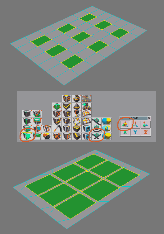
Finis: when you use the point scale in edit mode, you have 2 way: in top view, the scale effect is allway like you show in your image. in perspective view, you can do what i did if you select object coordinate system before (right clik on the point scale icon). with this option, only the size of the polygon change not their position. If you select world coordinate system, it is the whole who change like if it is only one polygon and it is what you did.
Design - illustration - Animation
http://www.crea-vision.fr
User avatar
Finis
Captain
Posts: 5410
Joined: 21 May 2009, 18:26
Type the number ten into the box: 0
Location: America!

Re: How to construct this window.

Post by Finis »

Thanks! That worked fine.
Attachments
Image1.gif
Image2.gif
Image2.gif (11.02 KiB) Viewed 5132 times
I prefer dangerous freedom over peaceful servitude. -- Thomas Jefferson/Jean Jacques Rousseau
User avatar
marcel
Captain
Posts: 2247
Joined: 21 May 2009, 19:52
Type the number ten into the box: 0
Location: paris - France

Re: How to construct this window.

Post by marcel »

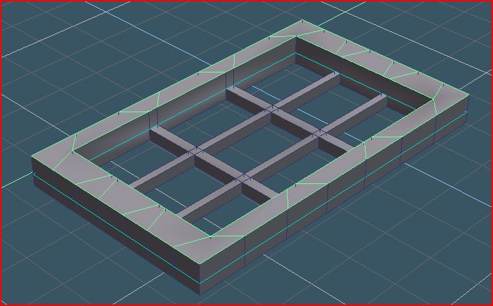
Now you can reduce the thick bars, then select the edge of the windows and sweep again to finish the windows (A).
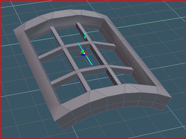
also, you can use the bend tool to curve the windows (B) to create a tower or another thing... ;)
Attachments
A.jpg
B.JPG
Design - illustration - Animation
http://www.crea-vision.fr
User avatar
spacekdet
Captain
Posts: 1810
Joined: 27 May 2009, 15:00
Type the number ten into the box: 10
Location: On the day shift at the Utility Muffin Research Kitchen

Re: How to construct this window.

Post by spacekdet »

I'll throw in another technique in the spirit of 'more than one way to skin a cat'
User avatar
marcel
Captain
Posts: 2247
Joined: 21 May 2009, 19:52
Type the number ten into the box: 0
Location: paris - France

Re: How to construct this window.

Post by marcel »

There is so many way to do the same thing...it is because we have not the same brain! :D
Design - illustration - Animation
http://www.crea-vision.fr
fahembree
Chief Petty Officer
Posts: 108
Joined: 22 May 2009, 02:28

Re: How to construct this window.

Post by fahembree »

Marcel,
Thanks, I can do that now. See attached window.
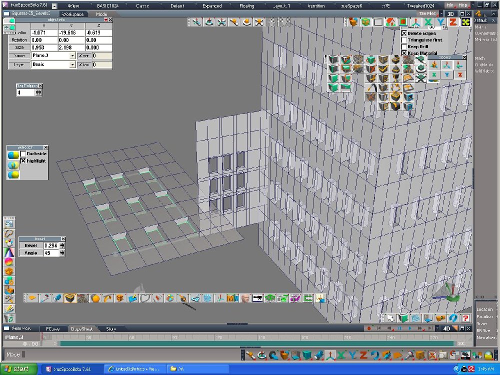
In all this expermenting iy seems you could also just use the bevel command on selected ploygons. :D
Attachments
windows.jpg
Bevel.jpg
User avatar
Finis
Captain
Posts: 5410
Joined: 21 May 2009, 18:26
Type the number ten into the box: 0
Location: America!

Re: How to construct this window.

Post by Finis »

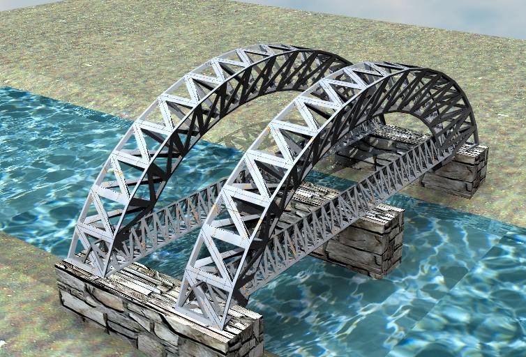
A bridge with Spacekdet's method.
Attachments
bridge.jpg
I prefer dangerous freedom over peaceful servitude. -- Thomas Jefferson/Jean Jacques Rousseau
myeakey
Petty Officer Third Class
Posts: 13
Joined: 22 Jul 2009, 19:07

Re: How to construct this window.

Post by myeakey »

Just a quick question. I did the tutorial and it was great. But how do you control the quad divide? The reason I am asking is that I keep getting an extra row and column where as all the images shows an even border.
User avatar
Finis
Captain
Posts: 5410
Joined: 21 May 2009, 18:26
Type the number ten into the box: 0
Location: America!

Re: How to construct this window.

Post by Finis »

Myeakey, I had that problem too. I selected and deleted part of the object in point edit mode to correct it.
I prefer dangerous freedom over peaceful servitude. -- Thomas Jefferson/Jean Jacques Rousseau
User avatar
marcel
Captain
Posts: 2247
Joined: 21 May 2009, 19:52
Type the number ten into the box: 0
Location: paris - France

Re: How to construct this window.

Post by marcel »

I don't understand your problem of row and column. maybe if you post a screenshot of the problem i can help you.
Design - illustration - Animation
http://www.crea-vision.fr
myeakey
Petty Officer Third Class
Posts: 13
Joined: 22 Jul 2009, 19:07

Re: How to construct this window.

Post by myeakey »

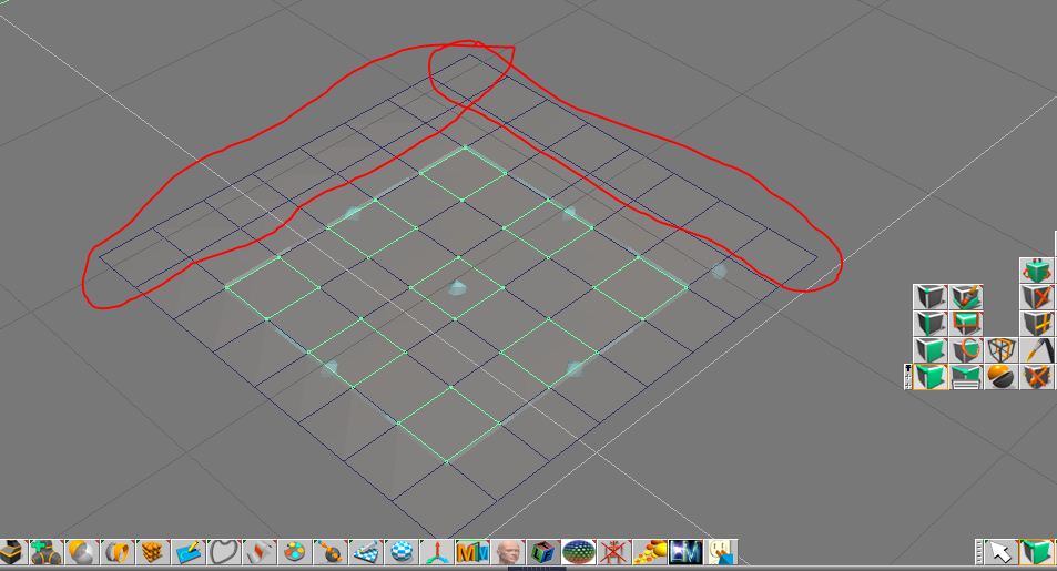
Here is the screenshot. I have circled in red the extra column and row when I use quad divide. It would appear that this would always be the case when using it.

Mike
Attachments
Quad.JPG
User avatar
marcel
Captain
Posts: 2247
Joined: 21 May 2009, 19:52
Type the number ten into the box: 0
Location: paris - France

Re: How to construct this window.

Post by marcel »

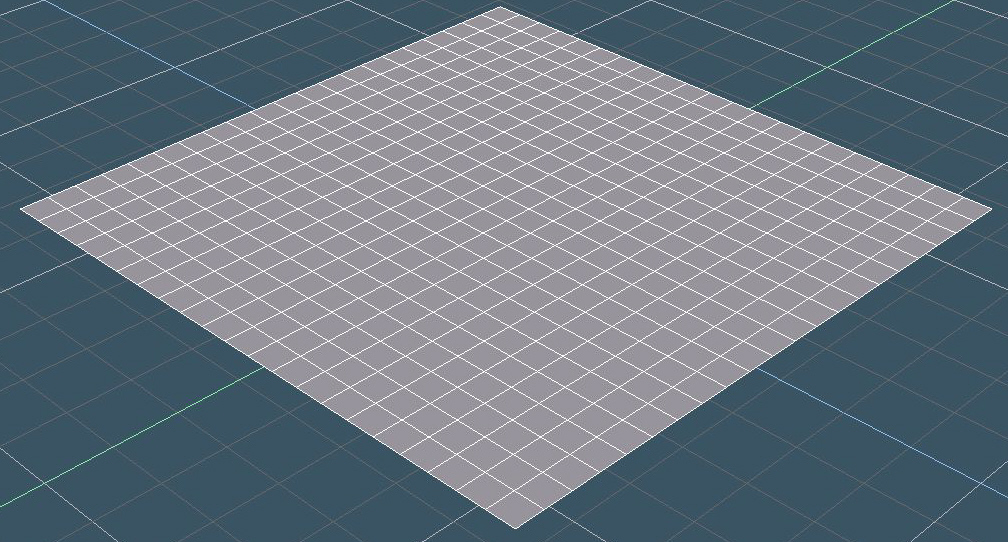
For your example, you need a resolution of 7X7 and quad divide is not the solution. Rigth click on the plane icon and choose 7 for the resolution (don't forget to active "single sided" above).
Attachments
plane.jpg
Design - illustration - Animation
http://www.crea-vision.fr
myeakey
Petty Officer Third Class
Posts: 13
Joined: 22 Jul 2009, 19:07

Re: How to construct this window.

Post by myeakey »

Thank you Marcel.

It didn't occur to me to check there. That makes it easier.

Mike
User avatar
Finis
Captain
Posts: 5410
Joined: 21 May 2009, 18:26
Type the number ten into the box: 0
Location: America!

Re: How to construct this window.

Post by Finis »

Looks like the number of polygons needed in a direction is 2W + 1 where W = the number of windows.

So a 4 x 4 block of windows needs 2x4 + 1 = 9 polygons per side.
I prefer dangerous freedom over peaceful servitude. -- Thomas Jefferson/Jean Jacques Rousseau
myeakey
Petty Officer Third Class
Posts: 13
Joined: 22 Jul 2009, 19:07

Re: How to construct this window.

Post by myeakey »

You are right. I just did 4x4 and 2x2 windows.

Return to “TechForum”